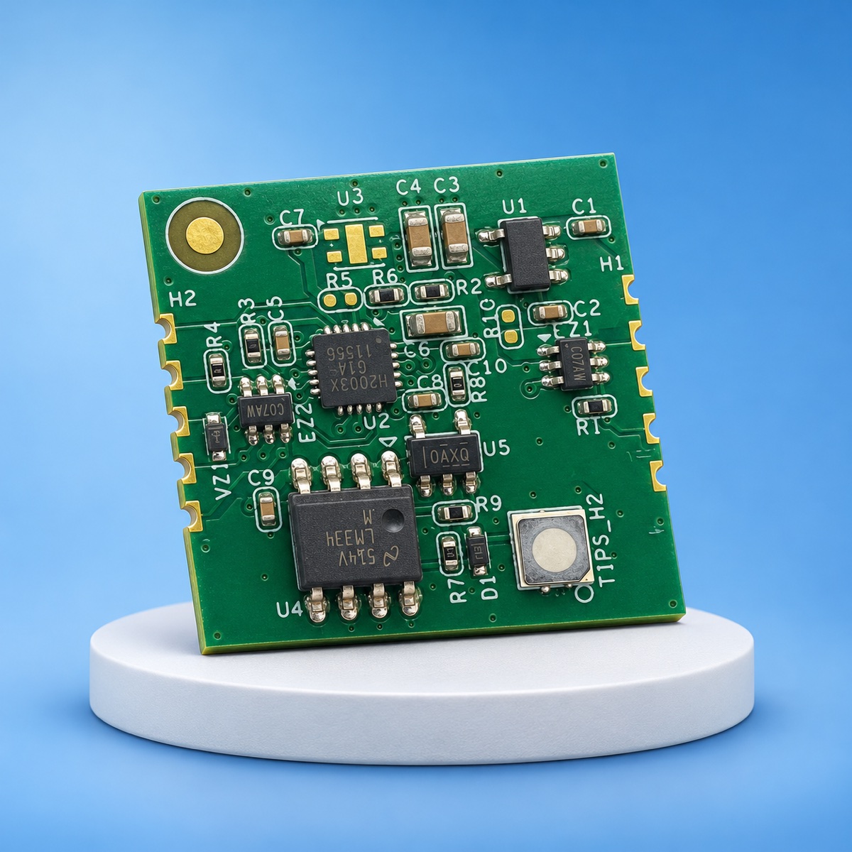
BSM3 hydrogen alarm module
A 20 × 20 mm PCB module with a 3.3 V GPIO alarm output.
- Alarm setpoint
- 500 ppm H₂
- Typical current
- <100 µA
- Module size
- 20 × 20 mm
Module specifications
| Alarm setpoint | 500 ppm H₂, set by TIPS before shipment |
|---|---|
| Factory test | Alarm ≤30 s at 4000 ppm H₂ |
| Calibration | Each module calibrated before shipment |
| Sampling rate | ≥0.5 Hz |
| Standard | Push-pull GPIO, 3.3 V: High when alarm is active, Low when inactive or cleared |
|---|---|
| Project options | UART or CAN — project development and validation required |
| Supply | 5 V |
|---|---|
| Current | <100 µA (typical) |
| Size | 20 × 20 mm |
| Supply format | PCB module, without enclosure |
| Temperature | -10 to 50 °C |
|---|---|
| Humidity | 20–80% RH, non-condensing |
| Damp heat test | 85 °C / 85% RH, 1,000 h |
|---|---|
| Result | Alarm function normal, no recalibration required |
| Source | TIPS internal test |
Pinout
Standard integration uses the five pins on the right edge.
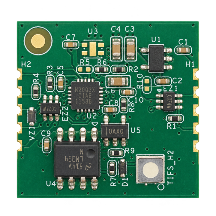 1 · +5 V2 · Heartbeat3 · Alarm4 · Mode5 · GND
| 1 · Top | +5 V supply |
|---|---|
| 2 | Heartbeat output |
| 3 | Alarm output (3.3 V GPIO, active high) |
| 4 | Mode — details provided with the datasheet |
| 5 · Bottom | GND |
Left-edge pads are for programming, debug and serial access, and are not used in standard integration.
Need the mechanical drawing or datasheet?
Tell us briefly about your application and we will send them by email.
Request the datasheet →